Description
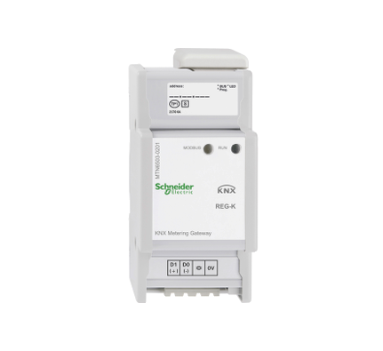
The KNX Metering Gateway Modbus REG-K is a gateway between a Modbus installation and the KNX bus.
The device transmits measured power and consumption values from connected Modbus power counters to the KNX bus. These power counter data can be used to evaluate, visualise, or reduce the power consumption in your KNX installation. Up to ten Modbus counters can be connected to the gateway in parallel with RTU transfer protocol. These counters send data to the KNX via the gateway. The gateway always works in master mode, and the connected Modbus devices work in slave mode. Communication from KNX to the Modbus is not possible. The ETS application has pre-programmed templates for 17 different Schneider Electric models of Modbus counters. In ETS, a corresponding template can be assigned to each connected Modbus counter. The corresponding Modbus registers are then automatically assigned to the communication objects on the KNX side.
The following models of Schneider Electric Modbus counters are supported:
■ PM9C universal meter
■ PM210 universal meter
■ PM710, PM750 universal meters
■ PM810, PM820, PM850, PM870 universal meters
■ PM1200, PM6200 universal meters
■ iEM3150, iEM3155, iEM3250, iEM3255 energy counters
■ PM3250, PM3255 universal meters
■ SIM10M Smart Interface Module
For Modbus devices without a template, up to 40 Modbus registers can be directly assigned to the communication objects on the KNX side.
The device is supplied with power via the KNX bus.
With integrated bus coupler. For installation on DIN rails TH35 according to EN 60715. The bus is connected using a bus connecting terminal.
With screw terminals.
KNX software functions: Modbus communication settings (baud rate, parity, delays). Selection of pre-programmed templates for 17 Modbus counters with detection of: voltage (phase 1-3), current (phase 1-3), frequency, power factor, active power, reactive power, apparent power, active energy, reactive energy, 6 binary counters, 2 analogue inputs (using Smart Interface Module SIM10M template). In addition to the template, direct access to Modbus registers and manual assignment of the register values to communication objects are possible. Diagnostic function: active and passive evaluation of errors in the Modbus installation. All values can be reset by a reset object.
Device width: 2.5 modules = approx. 44 mm


